Neal's Personal Page
Project ROBOX
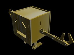
A 3-D animation video advertisment of ROBOX. I made it by using 3ds-max
Project Overview
Project ROBOX is a design and build project by a group of student in the Joint Programme of BUPT & QMUL. The aim of this project is to design and make a electronic clock by using 7400 series integrated circuits. In this project I worked as a team leader with 10 colleagues. This project started in June 2011 and end in September 2011.
During 3 months time, our team designed a clock with multiple functions including an alarm clock and a fast ,clear, and accurate time adjustment interface. Finally we build a clock including 80 discrete ICs each with only basic logic or register functions. These ICs were solderned on 5 different circuit board according to the different function groups they belong to. The boards were connected together with IDE bus cables which is quite commonly used in computers.
Key Challenges

There're a lot of technical challenges that we met building the clock. The followings are those that left me with deepest impression.
Debouncing Button
The first problem that we met is to debounce the buttons. As the human hand is not steady when press a button, sometimes the button might be triggered multiple times when you press on it.

The simplest idea is to build a lowpass filter to screen off the unnecessary vibration. After doing several experiments, we found that the analogue filter that we designed has a poor performance and was not stable all the time. Therefore, we turned to design a digital circuit to debounce the button.
The basic idea is very simple. Instead of using a filter, we then used a counter this time. The counter with a input of a rapidly fliping square wave signal will have an n-th order of frequcncy division on its n-th digit. Therefore any input signal that is shorter than the time defined by the counter and input clock will be regard as a bounce and be ignored.
The figure on the right shows the final design of our debouncing circuit. We chose a 16 Hz clock to restric the minimum time window for a button input, and used a d-latch to buffer the input.
Control Unit
The state machine of the clock is shown in the figure on the right. The circles stands for the differen states that the clock will work on. The arrows each labled with a signal stands for the transformation between each states triggered by different events.

There "Normal" mode is the mode in which the clock runs without any interruption, i.e. the display show the current time. There is a button called "Mode" which can be pressed by a user to switch between different mode.
Triggered by "Mode" button, the state machine can switch among "Modify Alarm", "Modify Clock", or "Normal". When in the state of "Modify Clock" or "Modify Alarm", the user can further decide whether to adjust hour or minute by press "Set" button, then either the hour digits or the minute digets will flash denoting that the digit is being set. Then the user can press and hold "+" button to adjust time.
There is another state triggered by statemachine itself instead of any user input called "Alarm Ring". When the time comes to the time stored in the alarm clock, this state will be triggered. Then the user can decide to press set to clear this state and switch back to normal mode or to ignore the alarm because the alarm will cancle itself afer ringing for 32 seconds.
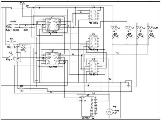
The figure above show how we designed our control unit that runs the function of the state machine. The two 74-ls-74 Dual D-Flipflop worked as the register of the state machine storing the current state. Other component 74-ls-86(XOR), 74-ls-00(NAND),and 74-ls-04(NOT) are the next-stage form the next-stage logic. The CD-4020(14 bits ripple carry counter) works as the frequency divider that provide the clock signal for the "Press and hold" function.
Bus Structure
In order to use only one display board to show multiple information(The current time and the time for the alarm clock), two sets of registers should be connected to the display at the same time. Also an control logic is needed to decide which number to show on the display. Instead to use two set of designated lines for each function, our clock multiplex two signals on the same set of lines. Therefore the two signals shares the same physical connection on a Time Division Multiplex basis. As a consequence, we chose to use a bus line to implement all the connections among boards(We used 4 boards in our design).

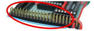
The figure shown above are an IDE bus cable and the picture of one of our boards. In order to put 6 BCD numbers onto a bus, 24 bits of bandwidth is needed(4 bits for each BCD number, 6 BCD numbers for the denotion of hh:mm:ss). The bus has also to hold other information like some control information and clock signals. So I decided to use An IDE bus which is extremely common in personal computers( As a matter of fact, I didn't buy new IDEs, instead I removed some from my old computer).
The End of the Story
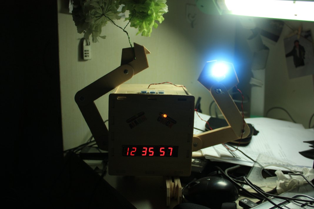
ROBOX stood on my dest for half a year and runned normally until one day it droped off my dest when I was showing its function to some of my friends. For some unknown reason, the clock gone mad and stared to jump between random number numbers(maybe some soldering node are short connected or some connection are broken). I hope that I will have time to fix it in the future. :(
You can watch this video here if you cannot access Youtube in your country.
Top Stories
Project Robox
Robox is a robot-like digital alarm clock designed and built by a group of student including me. We spent 2 months time building this building this machine out of several hundreds of discrete circuit components. Robox has a funny design of its appearance and a complecated design of its inner circuits. To see more about Robox, click here.

Team of 3 in ICM
In Febuary 2012, I together with Ms. Xun Dai (on my left) and Ms. Chun He(on my right) participated in the MCM/ICM mathematics modelling contest. We won a Meritorious prize with a model measuring the opportunity of commercial crime in a social network. To see more about our model, click here.
QR Motion
QR Motion is an ongoing project aiming on extending the capacity of current QR code. Instead of expanding QR code into larger area, QR Motion will extend the capacity of QR code by changing its pattern over time. Click here to see more about QR Motion.

Star Mysteria
In the Summer of 2012, Star Mysteria was released on Samsung App Store. This fancy Android application was developed by a group of student from Beijing. To see more about Star Mysteria, just click here.
email:haoxuan@nealwang.net Neal Wang 2014